In English I count 7 different ways to describe linear dimension directions:
Until BIM it didn't really matter. We used context to decide, usually the context of convention. But in BIM a lot of this context is lost. Schedules is an obvious example. For a start if there is no consistency you end up with 7 columns instead of 3. And the height of one component may be the same direction as the depth of another.
Another context lost is the region, country, and/or industry. Components are available world wide over the Internet. The convention in one region, or industry in one region, may be the opposite of another.
When I bring this problem up, no-one is interested. I haven't found a standard that addresses it (AutoDesk and ANZRS are silent). People say it doesn't matter. And it doesn't. It doesn't matter which definitions are used. What does matter is that the SAME definitions are used. And the most effective way to do this is to come up with simple rules that can be applied in any situation. That shouldn't be too hard. Or is it?
THE PROBLEM
The basis of the problem is, as I mentioned, humans understand direction names by context. Ignoring any particular industry conventions, the two common types of context are proportional and orientation.Proportional is when you define the longest dimension as length, next longest width, smallest depth. This the way most people normally think.
Orientation is when you define each direction by its orientation in respect to a reference direction. This could be the person looking at it (height is up/down), an absolution reference plane like the ground (height is forward/back), or a coordinate system (height is Z axis).
There is a very good investigation of this in the NatSPEC BIM Portal, under Workshop, Describing the dimensions of BIM objects.
SUGGESTION 1
Neil Greenstreet of NatSPEC, who authored Describing the dimensions of BIM objects, came up with a schema that tried to address how most people treat direction naming. A full description is on the NatSPEC BIM Portal, but in essence it is:For unfixed materials, use a proportion-based schema:
1. Use length, width and depth for cuboidal forms.
2. Use length, width and thickness for linear or planar forms.
For installed (or ready to install) elements, use a mixed orientation-based/proportion-based
schema:
1. Use height, width and depth for cuboidal forms.
2. Use height, length and thickness for vertical planar forms.
3. Use width, length and thickness for horizontal planar forms.
Note: The difference between cuboidal forms and planar forms would need to be defined by
an agreed aspect ratio.
My feeling is this is too complicated. There are too many different rules. Also a proportion based schema will never work where components are parameter driven. You can't change the label of a parameter when its value becomes the second longest instead of the longest.
SUGGESTION 2
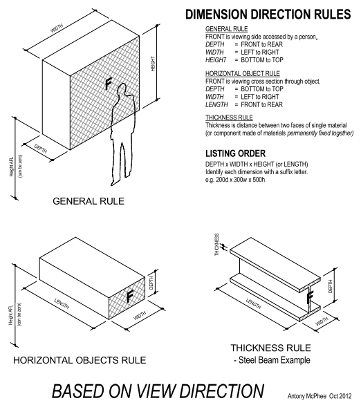
Thinking about this problem I believe the best approach is to use the idea of orientation only. The orientation that works in the majority of situations is based on standing in front of the object. You need no other context than the object and your (imagined) self.This rule works for most objects:
DEPTH = FRONT to REAR
WIDTH = LEFT to RIGHT
HEIGHT = BOTTOM to TOP
An alternative could be:
WIDTH = FRONT to REAR
LENGTH = LEFT to RIGHT
HEIGHT = BOTTOM to TOP
It doesn't really make much difference, but I stuck with the first rule as Revit uses these names in the casework template.
But some objects don't fit this rule. Objects like beams, ducts, floors. Although hard to precisely define, these types of objects could be described as having a horizontal orientation - dimensions parallel to the ground plane vary the most.
When standing in front of these objects the rule becomes:
DEPTH = BOTTOM to TOP
WIDTH = FRONT to REAR
LENGTH = LEFT to RIGHT
By defining 'Front' as the cross section (cut through smallest dimensions) the rule becomes:
DEPTH = BOTTOM to TOP
WIDTH = LEFT to RIGHT
LENGTH = FRONT to REAR
Which is a little closer to the first general rule.
Thickness deserves its own rule:
THICKNESS is distance between two faces of single material (or component made of materials permanently fixed together).
e.g. door panel, plasterboard, steel beam, duct insulation.
This is simpler than the NatSPEC way, but is it simple enough?
SUGGESTION 3
If direction rules are based on where 'Front' is, another approach is to have separate rules for where 'Front' is located. The advantage of this is that only one direction rule is required.
If we think of horizontally orientated objects as objects we have to bend to look down at, or to look up at, we could describe them as objects that are above or below. For example when looking down on a bucket or sink, or looking up at a beam or ceiling, Front to Rear becomes Depth in respect to the viewer.
So if we have one direction rule:
DEPTH = FRONT to REAR
WIDTH = LEFT to RIGHT
HEIGHT = BOTTOM to TOP
for objects above & below length is used instead of height:
LENGTH = BOTTOM to TOP
And two orientation rules:
GENERAL RULE
FRONT is side accessed by a person standing on the ground.
ABOVE & BELOW RULE
FRONT is top or bottom of object, bottom is cross section or end of object.

DIRECTION ORDER
An allied issue is the order of direction descriptions when naming objects. As this is not as critical I would term this a 'convention' rather than a standard.The AutoDesk Family guide recommends WxDxH (page 27).
In the Australian home construction industry windows are alphabetical (in English) HxW.
Australian steel uses DxW, timber sizes use DxB (for breadth, which is same as width).
I tend to use DxWxH as depth is lest likely to vary, width more likely, and height (or length) most likely. For example in a set of cupboards for each depth you have a range of widths and heights.
ANZRS recommends adding a letter after dimensions (e.g. 300d x 600w x 700h), which is eminently sensible whatever convention is used. But ANZRS don't make a recommendation for the actual order, which would be helpful.
CONCLUSION
I must admit, I don't feel I have come to a definitive answer. Perhaps there is not one. Maybe my 'rules' are really only useful as conventions, to be applied in the absence of clear definitions.What do you think? What conventions do you use?
Anthony,
ReplyDeleteI came to the same conclusion as you... there is no one answer. http://www.bimblog.ca/2012/03/whats-in-name.html
Consistency is the key and making everyone in your organization who creates content aware of how you want it done can make life much easier for the end user.
Nice piece Antony. The great thing about making a decision on your preferred format is that for your existing content it can be easier to rename your reference planes rather than changing parameter names which as you are aware can get messy.
ReplyDeleteCheers Pete
Anthony,
ReplyDeleteHave a look at this article:
http://bim.natspec.org/index.php?option=com_content&view=article&id=75:describing-the-dimensions-of-bim-objects&catid=41:workshop-documents&Itemid=55
It may not give you any more definitive answers but its been well thought through.
The article in your comment is the NatSPEC one I have a link for in my post. - "Describing the dimensions of BIM objects"
Delete